Ultravoilet(UV) Light Radiation Sensor
Outputs analog voltage as per UV radation falling on it. Easy to interface with any MCU with ADC.

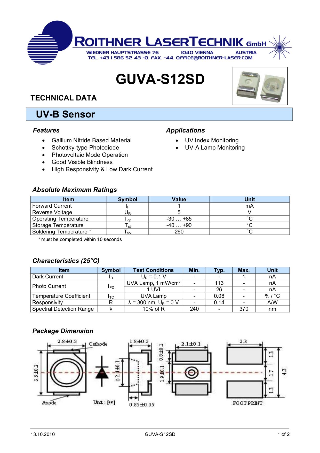
Extend your light-sensing spectrum with this analog UV sensor module. It uses a UV photodiode, which can detect the 240-370nm range of light (which covers UVB and most of UVA spectrum). The signal level from the photodiode is very small, in the nano-ampere level, so we tossed on an opamp to amplify the signal to a more manageable volt-level.
The UV Sensor is used for detecting the intensity of incident ultraviolet(UV) radiation like UV radation in sunlight. This form of electromagnetic radiation has shorter wavelengths than visible radiation. This module is based on the sensor GUVA-S12SD and SGM8521 Opamp, which has a wide spectral range of 200nm-370nm. The module outputs calibrated analog output voltage which varies with the UV intensity.
To use, power the sensor and op-amp by connecting V+ to 2.7-5.5VDC and GND to power ground. Then read the analog signal from the OUT pin. The output voltage is: Vo = 4.3 * Diode-Current-in-uA. So if the photocurrent is 1uA (9 mW/cm^2), the output voltage is 4.3V. You can also convert the voltage to UV Index by dividing the output voltage by 0.1V. So if the output voltage is 0.5V, the UV Index is about 5
Applications
- Plants growing environmental affects of Sunlight
- UV-A Lamp Monitoring
- UV Index Monitoring
- DIY UV electronic project
- Sunburn Alarm
Features
- Designed for high reliability and accuracy of measuring the UV index (UVI)
- Suitable for measuring the total amount of ultraviolet sunlight intensity or other light radation source.
- Output Suitable to match World Health Organization classification standard UV Index
- UV detection wavelength: 200-370nm;
- Fast response, full interchangeability;
Specifications
- Operating Voltage: 3.3V to 5V
- Output Voltage: 0V to 1V (0-10 UV Index)
- Response time: 0.5 Second
- Accuracy: +/- 1 UV Index
- Radation Wavelength: 200-370nm
- Operating Temperature: -20 degC to +85 degC
- Current Consumption: 5mA
- Dimensions: 20x15mm
Pinouts
| Pin Name | Details |
| OUT | Analog Output from 0 to 1V(1000mV) |
| VCC | +3.3V to 5V Regulated Power Input |
| GND | Common Power Ground |
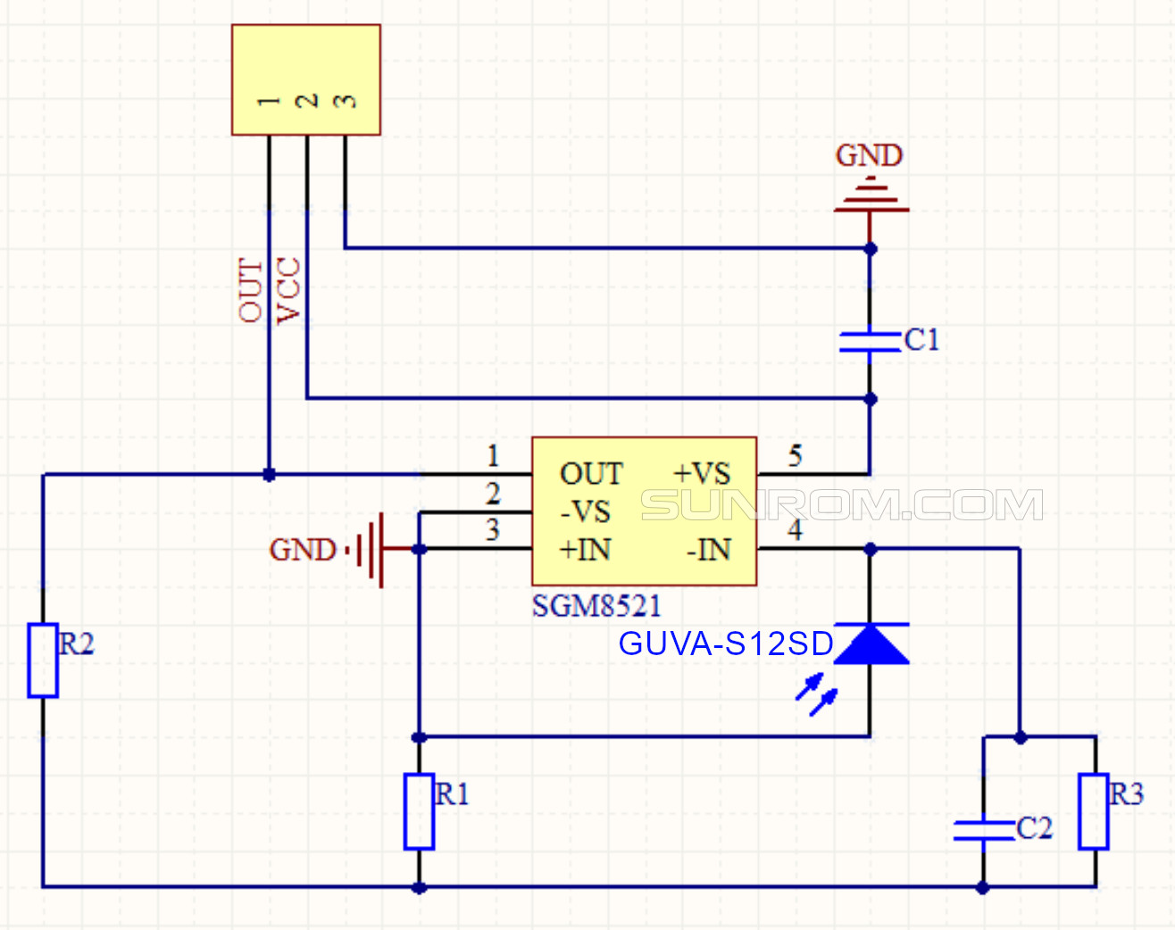
Board Schematic


Board Electronics
The UV Sensor module is based on the renowned sensor GUVA-S12SD from EOC (www.eocinc.com) . GUVA-S12SD is a Gallium Nitride material based Schottky-type photodiode, optimized for photovoltaic mode operation. Next main component is an Op-Amp IC SGM8521 from SGMICRO (www.sg-micro.com). The SGM8521 is a rail-to-rail input and output voltage feedback amplifiers offering low cost. This Op-Amp have a wide input common-mode voltage range and output voltage swing, and take the minimum operating supply voltage down to 2.1V and the maximum recommended supply voltage is 5.5V. Besides, SGM8521 provides 150kHz bandwidth at a low current consumption of 4.7 µA.

Here is the basic circuit diagram of the UV Sensor Module, In the circuit PD1 is the GUVA-S12SD, and U1 is the SGM8521. Rx is 10M.

/*
 * Sensor: GUVA-S12SD
 * Sensor     Arduino
 * SIG    ->    A0
 * GND    ->    GND
 * VCC    ->    5V
 */
int sensorValue;
long sum = 0;
int vout = 0;
int uv = 0;

void setup() {
  Serial.begin(9600);
}

void loop() {
  sensorValue = 0;
  sum = 0;
  for (int i = 0 ; i < 1024 ; i++ ) {
    sensorValue = analogRead(A0);
    sum = sensorValue + sum;
    delay(2);
  }
  vout = sum >> 10;
  vout = vout * 4980.0 / 1024;
  Serial.print("The Photocurrent value:");
  Serial.print(vout);
  Serial.println("mV");
  if (vout < 50) {
    uv = 0;
  }
  else if (vout < 227) {
    uv = 1;
  }
  else if (vout < 318) {
    uv = 2;
  }
  else if (vout < 408) {
    uv = 3;
  }
  else if (vout < 503) {
    uv = 4;
  }
  else if (vout < 606) {
    uv = 5;
  }
  else if (vout < 696) {
    uv = 6;
  }
  else if (vout < 795) {
    uv = 7;
  }
  else if (vout < 881) {
    uv = 8;
  }
  else if (vout < 976) {
    uv = 9;
  }
  else if (vout < 1079) {
    uv = 10;
  }
  else {
    uv = 11;
  }
  delay(20);
  Serial.print("UV Index = ");
  Serial.println(uv);
}