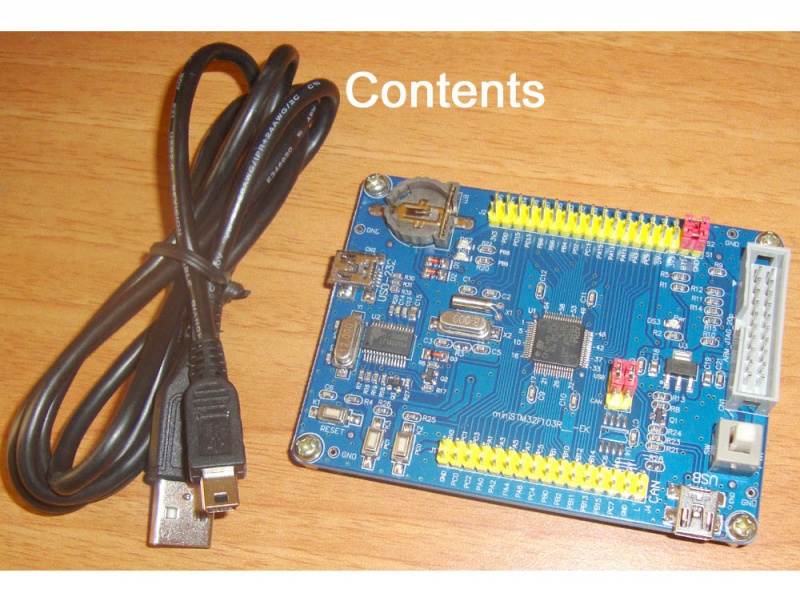
STM32F103RBT6 Dev Board
STM32F103RB Mainstream Performance line, ARM Cortex-M3 MCU, LQFP-64, 32 bit, 72 MHz, 128KB Flash, 20KB RAM, CAN, I2C, SPI, USART, USB Device


The ARM Cortex-M3 processor has been developed to provide a low-cost platform that meets the needs of MCU implementation, with a reduced pin count and low power consumption, while delivering outstanding computational performance and an advanced system response to interrupts. The ARM Cortex-M3 32-bit RISC processor features exceptional code efficiency, delivering high performance which is expected from an ARM core in the memory size usually associated with 8-bit and 16-bit devices. The STM32F103 Performance Line family has an embedded ARM core and is therefore compatible with all ARM tools and software. It combines the high performance ARM Cortex-M3 CPU with an extensive range of peripheral functions and enhanced I/O capabilities. This is a good start-up board for learning the new ST Cortex-M3 based microcontrollers STM32F103RBT6. The headers with all microcontrollers port output allows you to easily implement your own experiments and add-ons.

Features
- STM32F103RBT6 ARM 32-bit CORTEX M3™ with 128K Bytes Program Flash, 20K Bytes RAM, USB, CAN, x2 I2C, x2 ADC 12 bit, x3
- UART, x2 SPI, x3 TIMERS, up to 72MHz operation
- Standard 2x10 pin ARM JTAG connector with Reset button
- The onboard crystal 32.768KHZ and 8MHZ
- On-board voltage regulator 3.3V with up to 800mA current AMS1117-3.3
- USB connector with USB-UART onboard
- All I / O all the leads, and mark the I / O name
- Supports USB power supply
- Status LED / Power supply LED
- 8 MHz crystal / 32768 Hz crystal and RTC backup battery connector
- Extension headers for all uC ports
Supports programming via USB, Do not need programmer or any jumper or switch setup.
Programming (Touch less by USB port)

Debugging by Keil ULINK2
Code examples provided in download


Chip Features
- ARM 32-bit Cortex™-M3 CPU Core
- 72 MHz maximum frequency,1.25 DMIPS/MHz (Dhrystone 2.1) performance at 0 wait state memory access
- Single-cycle multiplication and hardware division
- Memories
- 128 Kbytes of Flash memory
- 20 Kbytes of SRAM
- Clock, reset and supply management
- 2.0 to 3.6 V application supply and I/Os
- POR, PDR, and programmable voltage detector (PVD)
- 4-to-16 MHz crystal oscillator
- Internal 8 MHz factory-trimmed RC
- Internal 40 kHz RC
- PLL for CPU clock
- 32 kHz oscillator for RTC with calibration
- Low power
- Sleep, Stop and Standby modes
- VBAT supply for RTC and backup registers
- 2 x 12-bit, 1 μs A/D converters (up to 16 channels)
- Conversion range: 0 to 3.6 V
- Dual-sample and hold capability
- Temperature sensor
- DMA
- 7-channel DMA controller
- Peripherals supported: timers, ADC, SPIs, I2Cs and USARTs
- Up to 80 fast I/O ports
- 26/37/51/80 I/Os, all mappable on 16 external interrupt vectors and almost all 5 V-tolerant
- Debug mode
- Serial wire debug (SWD) & JTAG interfaces
- 7 timers
- Three 16-bit timers, each with up to 4 IC/OC/PWM or pulse counter and quadrature (incremental) encoder input
- 16-bit, motor control PWM timer with dead-time generation and emergency stop
- 2 watchdog timers (Independent and Window)
- SysTick timer 24-bit downcounter
- Up to 9 communication interfaces
- Up to 2 x I2C interfaces (SMBus/PMBus)
- Up to 3 USARTs (ISO 7816 interface, LIN, IrDA capability, modem control)
- Up to 2 SPIs (18 Mbit/s)
- CAN interface (2.0B Active)
- USB 2.0 full-speed interface
- CRC calculation unit, 96-bit unique ID
Using MCU-ISP to Load HEX Files
Connect Board to PC
Please make sure you have install PL2303 USB Driver already. Else you can see the download area and install.
Your board red jumpers should be setup like below.

Check device manager for COM port created
Once board is powered on it should show up in your computer device manager as a COM port.

Start ISP Software
Start MCU ISP software and it should have been setup like below.

You can find the LED HEX file in examples download. Then click Start ISP button. Once downloaded the two LEDs will blink alternately.
Creating HEX files in Keil ARM MDK
Code Examples download contains Keil ARM MDK project with below examples
Requirements
- Keil ARM MDK (Fill the form and download latest, Google for its Keygen to unlock full version)
Example: LED Demo
Locate UVision project file and open it in Keil like below.


UART-Polling Example

If you want to repeat the below message, then preset RESET button on board.

Debug with Keil Ulink2
Connect JTAG connector and USB connectors & Power on board.

Set Target Options