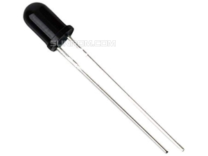
Phototransistor 5mm - Everlight PT333-3C Clear
Internal Photodiode + Amplifier combination feature in 5mm Package
Downloads
PT Datasheet & AppNotes
Phototransistor 5mm - Everlight PT333-3C Clear
Sunrom Product Code for Ordering:
3533
Phototransistors are photodiode-amplifier combinations
integrated within a single silicon chip. These are combined to
overcome the major fault of photodiodes: unity gain. Many
applications demand a greater output signal from the photodetector
than can be generated by a photodiode alone. While the signal
from a photodiode can always be amplified through use of an
external op-amp or other circuitry, this approach is often not as
practical or as cost-effective as the use of phototransistors. The
phototransistor can be viewed as a photodiode whose output
photocurrent is fed into the base of a conventional small-signal
transistor.
Phototransistors can be used as ambient-light detectors. When used with a controllable light source, typically an IRED, they are often employed as the detector element for optoisolators and transmissive or reflective optical switches.
This is why manufacturers offer infrared-emitting diodes. Their goal is to maximize the signal-to-noise ratio, by using an emitter with the best match to the phototransistor response. However, note the response is very broad and virtually any light source will work.
Basically, a phototransistor can be any bipolar transistor with a transparent case. There are some variations provide advantages. For example, a focusing lens can be built into the case for directional sensitivity. Coatings can be applied to block some higher or lower wavelengths. The transistor itself may provide higher gain, or higher frequency, or lower capacitance, etc.
Graph of relative response across the spectrum

The diagram above illustrates the frequency response of silicon phototransistor junctions, along with the spectral output of an infrared LED.

A phototransistor works just like a normal (NPN) transistor, where the BASE current is multiplied to give the COLLECTOR current, except that in a Phototransistor, the BASE current is controlled by the amount of visible or Infrared light, which is why the device only needs 2 pins.
In the simple circuit above, assuming that nothing is connected to "Vout", the BASE current (controlled by the amount of light) will determine the COLLECTOR current, which is the current going through the resistor. Using Ohm law, V=I*R, therefore the voltage at Vout will move up & down based on the amount of light. You can connect this to an OPAMP to boost the signal or directly to an Analog input of a microcontroller. You will then need to program the ADC unit of your microcontroller to read this analog voltage and use it in your code.
Phototransistors can be used as ambient-light detectors. When used with a controllable light source, typically an IRED, they are often employed as the detector element for optoisolators and transmissive or reflective optical switches.
Phototransistor Frequency Response
All silicon photosensors (phototransistors, etc.) respond to the entire visible radiation range as well as to infrared. In fact, all diodes, transistors, Darlingtons, triacs, etc. have the same basic radiation frequency response. This response peaks in the infrared range.This is why manufacturers offer infrared-emitting diodes. Their goal is to maximize the signal-to-noise ratio, by using an emitter with the best match to the phototransistor response. However, note the response is very broad and virtually any light source will work.
Basically, a phototransistor can be any bipolar transistor with a transparent case. There are some variations provide advantages. For example, a focusing lens can be built into the case for directional sensitivity. Coatings can be applied to block some higher or lower wavelengths. The transistor itself may provide higher gain, or higher frequency, or lower capacitance, etc.
Graph of relative response across the spectrum

The diagram above illustrates the frequency response of silicon phototransistor junctions, along with the spectral output of an infrared LED.
Simple IR Sensor Circuit

A phototransistor works just like a normal (NPN) transistor, where the BASE current is multiplied to give the COLLECTOR current, except that in a Phototransistor, the BASE current is controlled by the amount of visible or Infrared light, which is why the device only needs 2 pins.
In the simple circuit above, assuming that nothing is connected to "Vout", the BASE current (controlled by the amount of light) will determine the COLLECTOR current, which is the current going through the resistor. Using Ohm law, V=I*R, therefore the voltage at Vout will move up & down based on the amount of light. You can connect this to an OPAMP to boost the signal or directly to an Analog input of a microcontroller. You will then need to program the ADC unit of your microcontroller to read this analog voltage and use it in your code.

