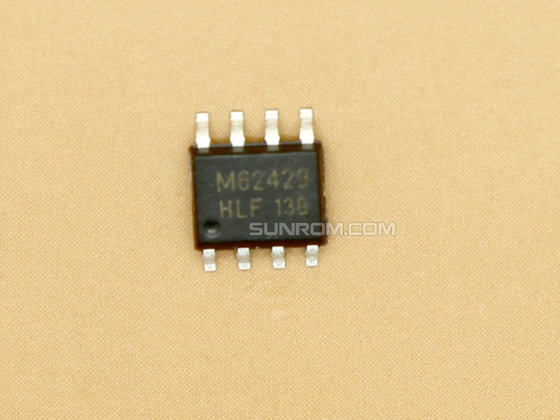
M62429 - Digital Pot
FM62429, SOIC8, Dual channel electronic volume controlled with 2-wire serial data(its not I2C).
Downloads
M62429 Datasheet
M62429 - Digital Pot
Sunrom Product Code for Ordering:
4014


Arduino Example
/*
Example to test M62429
*/

int x=0;
int VolumePinDAT=7; // connect to DATA
int VolumePinCLK=6; // connect to CLOCK


void setup (void)
{
  pinMode(VolumePinDAT, OUTPUT);
  pinMode(VolumePinCLK, OUTPUT);
}

void loop (void)
{

  // sweep from quiet to loud
  for (x=0;x<=100;x++)
{
  setVolume(x);
  delay(100);
  }

  // sweep back
  for (x=100;x>=0;x--)
{
  setVolume(x);
  delay(100);
  }
}


// this function does the job
void setVolume (uint8_t volume)
{
	uint8_t bits;
	uint16_t data = 0; // control word is built by OR-ing in the bits

	// convert attenuation to volume
	volume = (volume > 100) ? 0 : (((volume * 83) / -100) + 83); // remember 0 is full volume!
        // generate 10 bits of data
	data |= (0 << 0); // D0 (channel select: 0=ch1, 1=ch2)
	data |= (0 << 1); // D1 (individual/both select: 0=both, 1=individual)
	data |= ((21 - (volume / 4)) << 2); // D2...D6 (ATT1: coarse attenuator: 0,-4dB,-8dB, etc.. steps of 4dB)
	data |= ((3 - (volume % 4)) << 7); // D7...D8 (ATT2: fine attenuator: 0...-1dB... steps of 1dB)
	data |= (0b11 << 9); // D9...D10 // D9 & D10 must both be 1

	for (bits = 0; bits < 11; bits++) { // send out 11 control bits
		delayMicroseconds (2); // pg.4 - M62429P/FP datasheet
		digitalWrite (VolumePinDAT, 0);
		delayMicroseconds (2);
		digitalWrite (VolumePinCLK, 0);
		delayMicroseconds (2);
		digitalWrite (VolumePinDAT, (data >> bits) & 0x01);
		delayMicroseconds (2);
		digitalWrite (VolumePinCLK, 1);
	}
	delayMicroseconds (2);
	digitalWrite (VolumePinDAT, 1); // final clock latches data in
	delayMicroseconds (2);
	digitalWrite (VolumePinCLK, 0);
	//return data; // return bit pattern in case you want it :)
}

